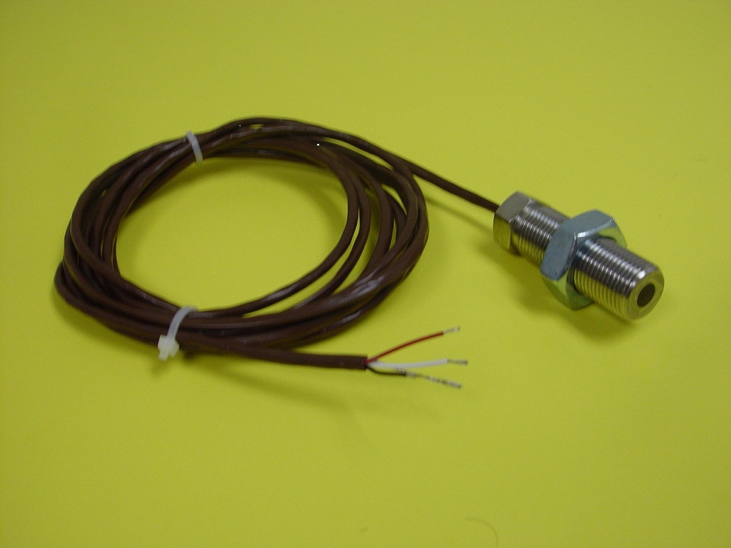
Hall Effect Speed Sensor By SENSORONIX USA Circuit Diagram 3 Phase BLDC with 3x Hall sensors in 120 degrees, 2 pole-pair; The image below shows the situation: I have setup a timer in XOR mode in the micro. The PSC is [19 - 1] and the Counter Period is [10000 - 1] while the timer clock is 80MHz. My motor has the maximum speed of 3000RPM. The timer is setup in XOR mode and with each transition generates
Hello, hope you are well. I have a project in electronics in which I need to measure the rotational speed of a fan using a hall effect sensor and display this speed on a 16x2 lcd. I have no problem with the display on the LCD. But I don't know how to go about it with the hall effect sensor to be able to measure the rotational speed of a fan.
RPM Measurement Using Hall Sensor and Arduino Circuit Diagram
Hello, I am trying to measure the speed of a bicycle wheel using a hall effect sensor. I am using the code below and get the RPM which I then convert into m/s. However, I want the measurement to be more accurate. Using my code the RPM changes by 60 which is roughly 2 m/s. I want a more accurate speed measurements with not such big intervals The GND of the sensor is connected to the GND pin on the Arduino. The Vout or signal pin of the Hall effect sensor is connected to the Arduino's interrupt pin (digital pin 2). Furthermore, a 10K resistor is connected between the VCC and Vout pins of the Hall effect sensor. This is done to pull the output of the Hall effect sensor to 5V.

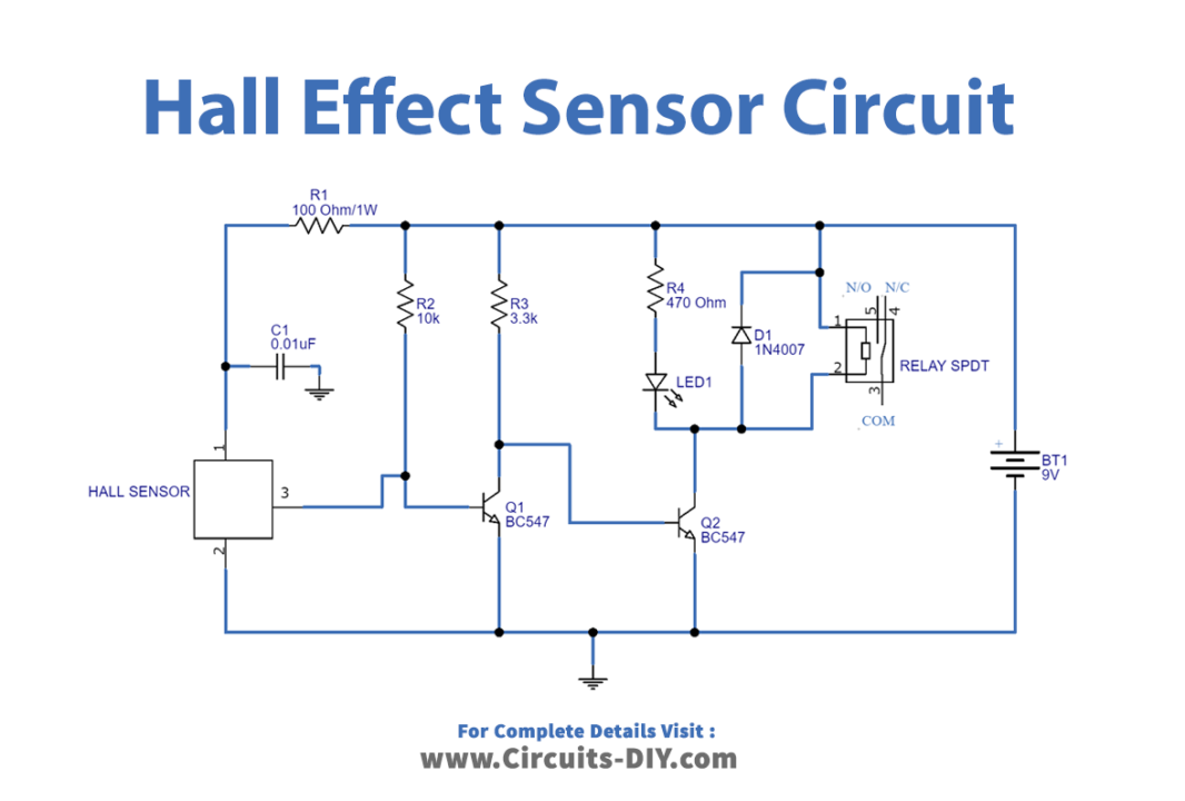
One of the popular applications of hall effect sensors is in automotive systems where they are used to detect position, measure distance and speed. They are also used in modern devices like smartphones and computers and also used in different type of switches where the presence of a magnetic field is used to either activate or deactivate a circuit.
Using a Hall Effect Sensor with Arduino Circuit Diagram
Use the long 5-pin Wireling cable to connect the Hall-Effect Sensor to Port 0 on the Wireling TinyShield. Connect the TinyScreen+ to your computer via the micro USB cable. Step 2: Software Open your Arduino IDE and select the TinyScreen+ from Tools -> Board. Confirm that you are connected to the correct port.
